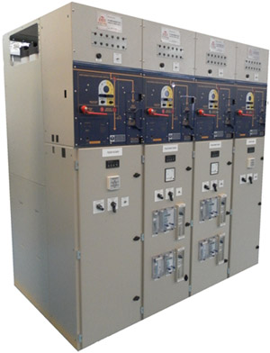
A market leader in 12kV switchgear, the Eclipse is designed to provide a lifetime of unrivalled service, bringing together one of the most advanced operating mechanisms available on the market today – the award winning magnetic actuator technology – with vacuum interruption and the simplicity of air insulation in a compact, fixed pattern design.
Appreciated throughout the distribution network and across every business sector, the Eclipse currently holds a dominant market position for indoor 12kV switchgear.
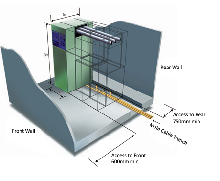
Dimension (In mm)
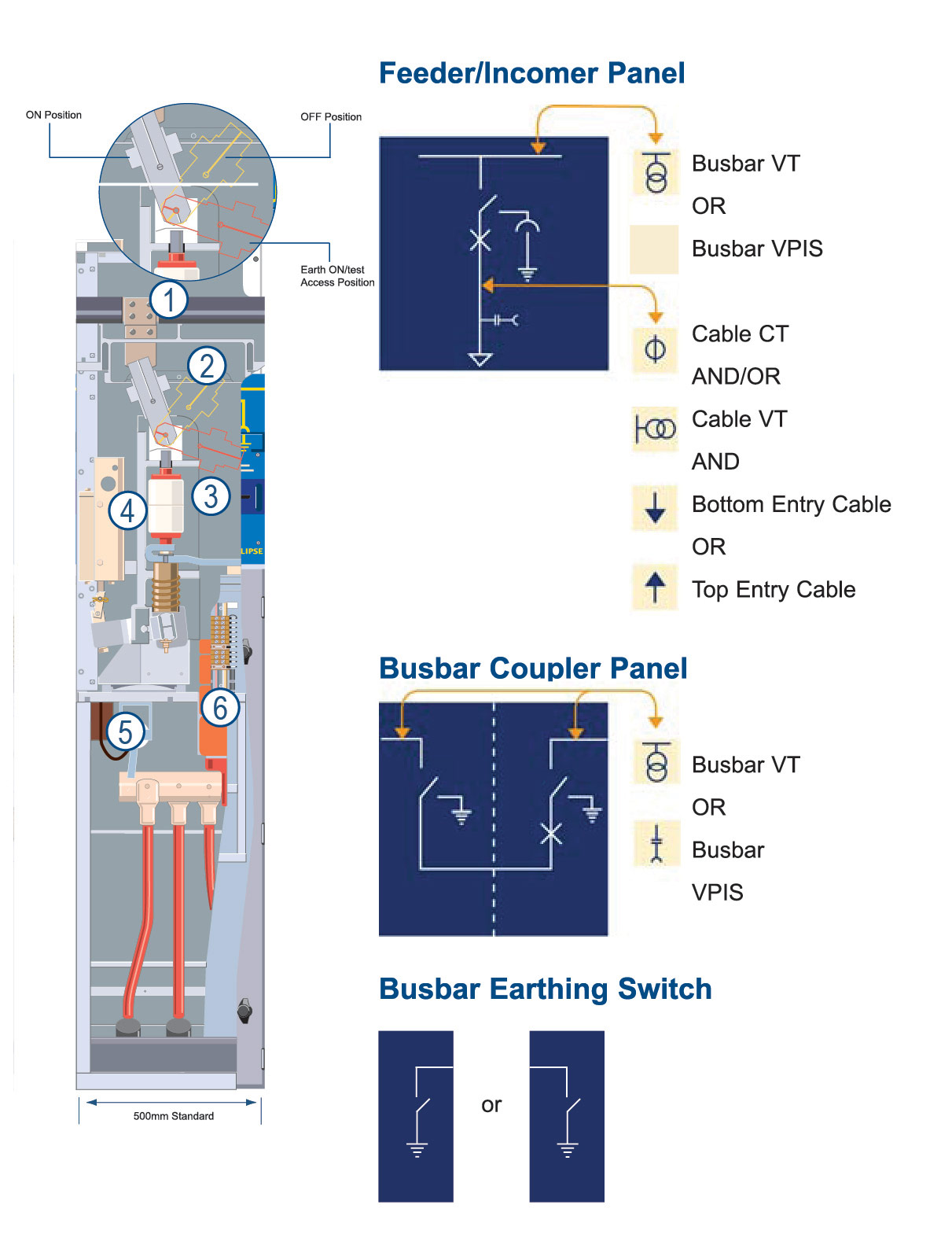
- Dimensions for a standard Eclipse feeder/incomer panel;
(a) 1162 (b) 2165 (c) 500
- Dimensions for a standard
Bus-section panel;
(a) 1162 (b) 2165 (c) 1000
- Dimensions for a Busbar earthing switch; (c) 325
- Dimensions for a single panel with Busbar VT; (b) 2500
- Dimensions for top entry cable; One cable per phase - (a) 1482
- Three cables per phase - (a) 1812
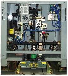
Eclipse Engineering Detail
- Sleeved busbars constructed from hard drawn, high
conductivity copper, and vermin proof covered joints, 1
with normal current ratings up to 2000A. The busbar
arrangement permits future expansion, at either end of 2
the switchboard.
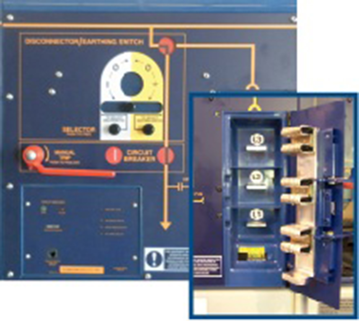
- Fully interlocked, manually operated 3-position disconnector including circuit earth and front panel cable
test access. The disconnector can be secured and 4
padlocked in all three positions: ‘on’, ‘off’ and ‘earth on/ test’, with its status indicated by animated front panel mimics.
- A single moulding supports the three phase vacuum
interrupter assembly, magnetic actuator mechanism and 6
one-piece drive beam. 5
- The patented single coil magnetic actuator mechanism is based on a solenoid plunger, held in the tripped or closed position by permanent magnets.
- Three phase cast resin voltage transformer, with manually operated off-load disconnector on the primary circuit.
- Generous CT accommodation enables complex protection schemes to be catered for in a single panel, whilst still allowing for a metering provision. The CT designs are rated in keeping with the short time withstand level of the equipment and comply with IEC 60044-1.
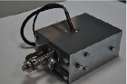
Unique Front Access Cable Testing Option:
- Avoids any contact with Live cables or busbars.
- Eliminates the need for Opening of rear covers to access live cables.
- Provides secure & mechanically interlocked front access contacts points to connect cable test equipment.
- Colour coded and suitably
labelled copper contacts
eliminates risk of improper
connections during testing
live cables.
| Rated Normal Current |
A |
630/1250 |
| Rated Voltage |
kV |
12 |
| Rated Frequency |
Hz |
50 |
| Rated BIL |
pk kV |
75 |
| Rated Power Frequency Withstand |
kV 1min |
28 |
| Rated Short-Time Withstand Current |
kArms 3secs |
25 |
| Rated Peak Making Current |
pk kA |
50/62.5 |
| Internal Arc Compliance |
kA 1sec |
25 |
| Rated Short Circuit Breaking Current |
kA |
20/25 |
| Degree of Protection * |
|
IP4X |
*Higher Ratings available on request
| Auxiliary Operating Supply |
125/110/48/30V dc |
| Typical Weight Range |
500 - 650kg |
| Busbars |
1250A |
Normal Service Conditions:
| Ambient air temperature |
-5ºC to +55ºC |
| Relative humidity |
<95% |
| Altitude |
<1000m |
Standards:
- IEC 62271-200, IEC 62271-100, IEC62271-102, IEC 62271-1
- ENA TS 41-36
 |
 |
 |
 |
| Switching Station |
Transport Applications |
Seconday Substation applications |
MOD |
| |
|
|
|
 |
 |
 |
 |
| Industrial |
Hospitals |
Education |
Commercial |
| |
|
|
|
 |
| Utilities |